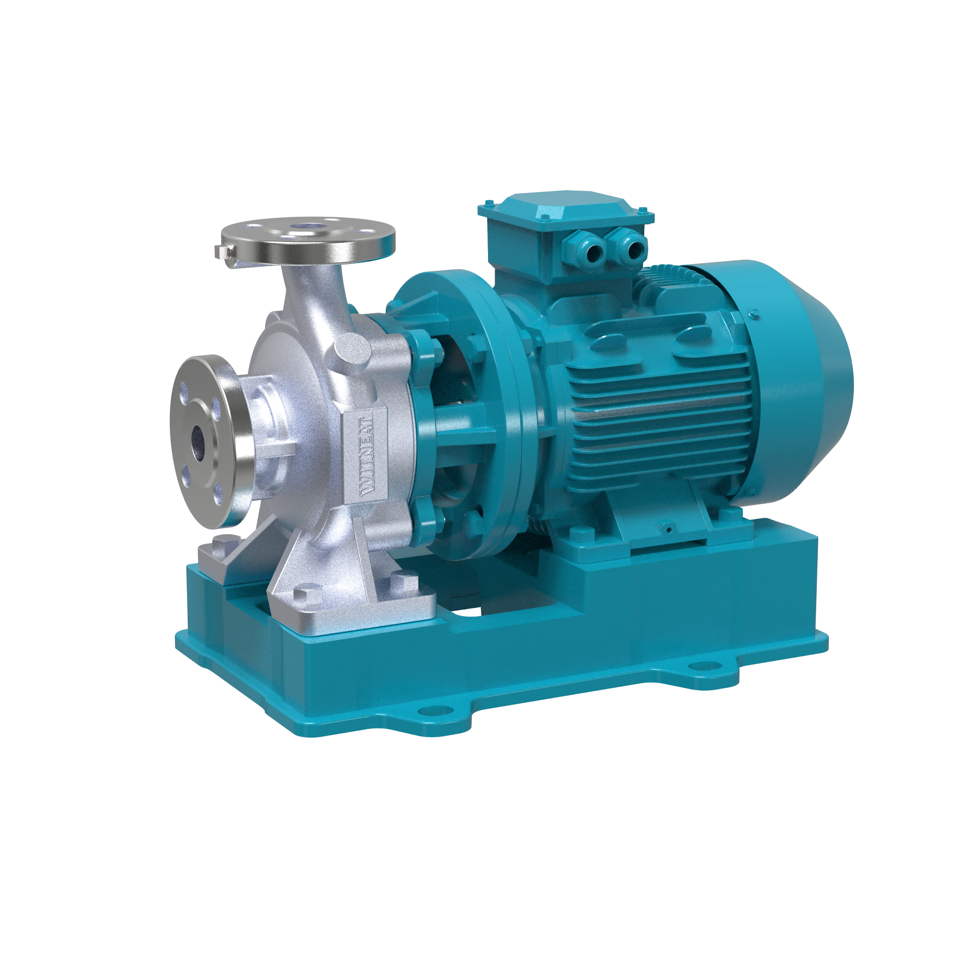


WYTCDLF
Head Range:9-120m Motor Power:0.55-110kW Inlet/Outlet Range:DN25-DN200 CDLF Pump
Head Range:9-120m
Motor Power:0.55-110kW
Inlet/Outlet Range:DN25-DN200
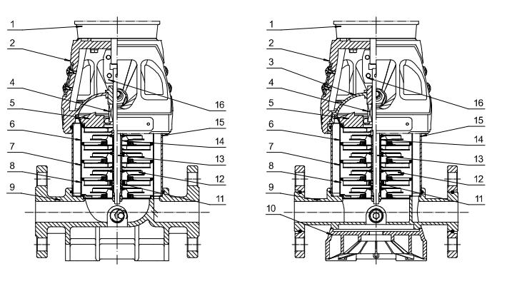
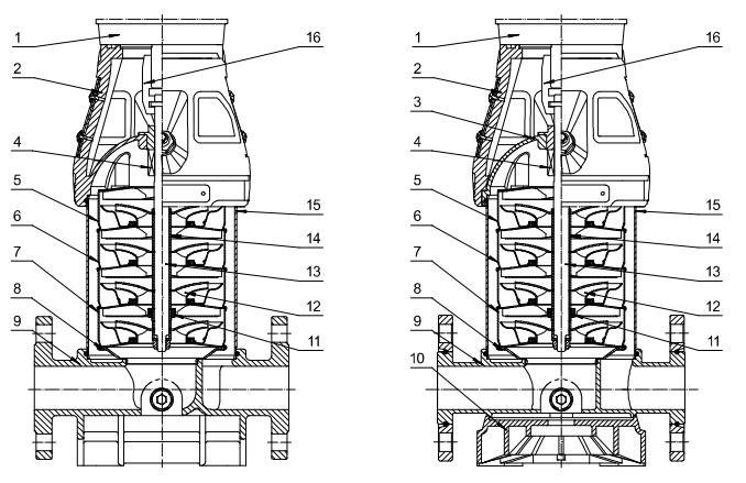
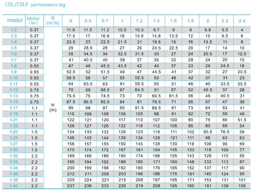
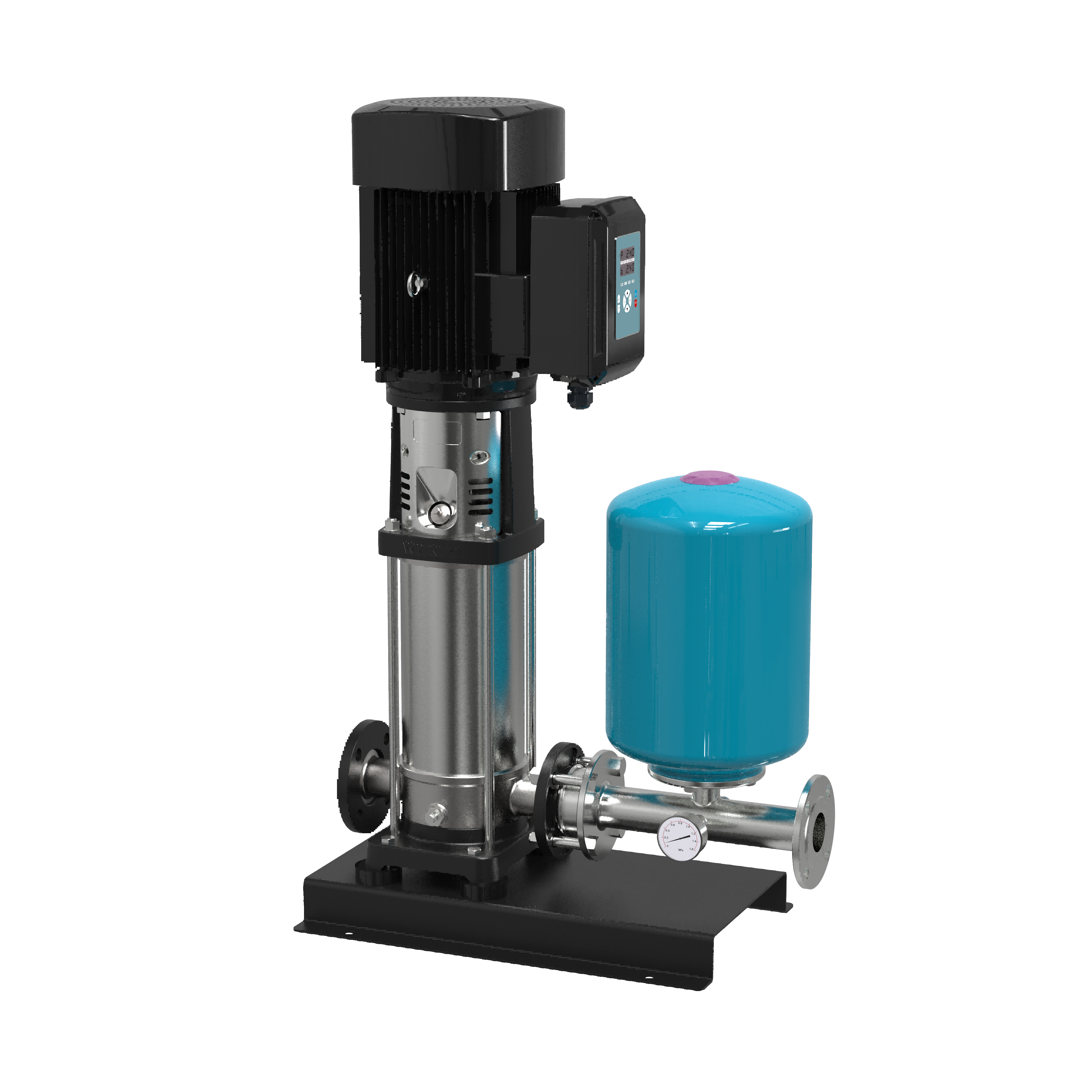
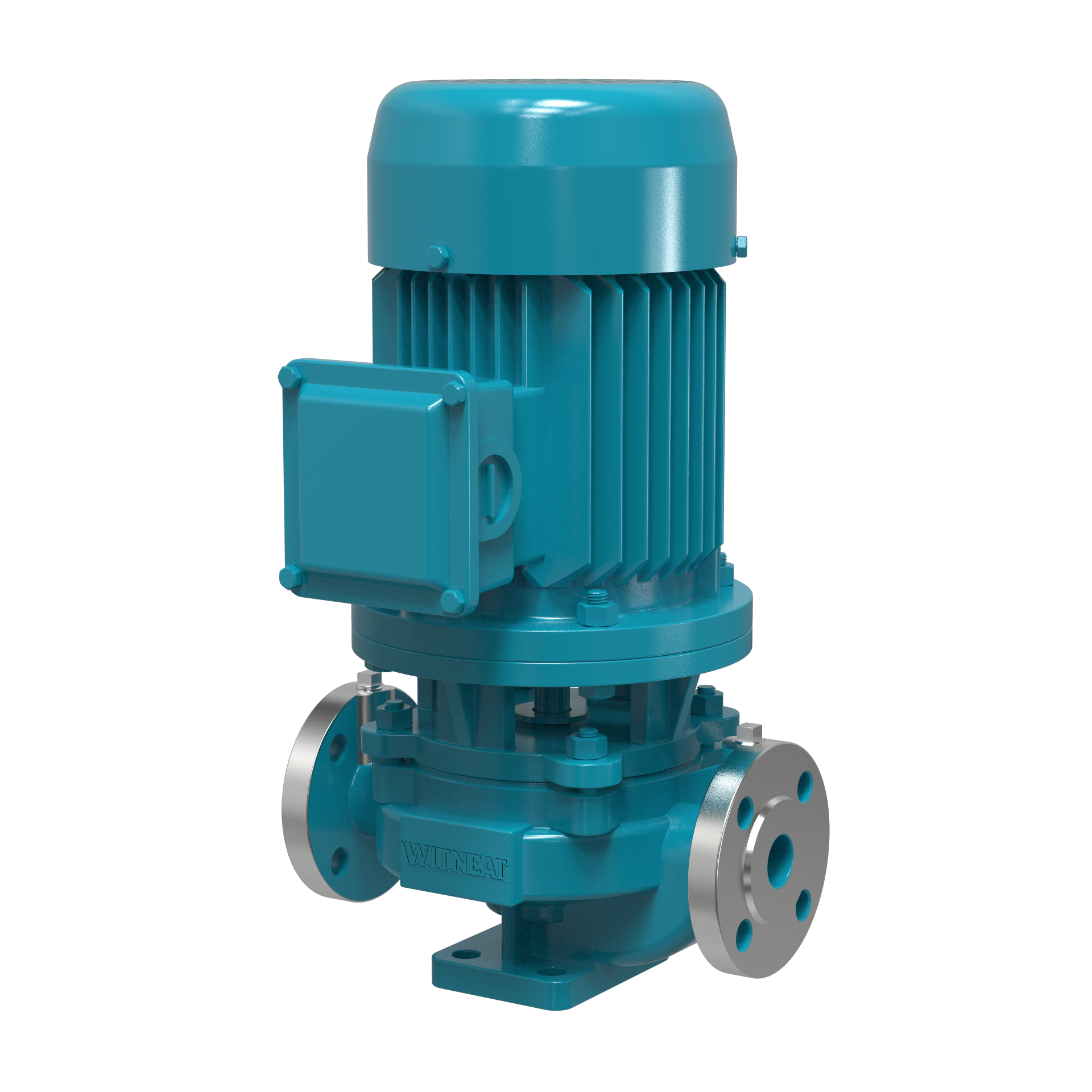
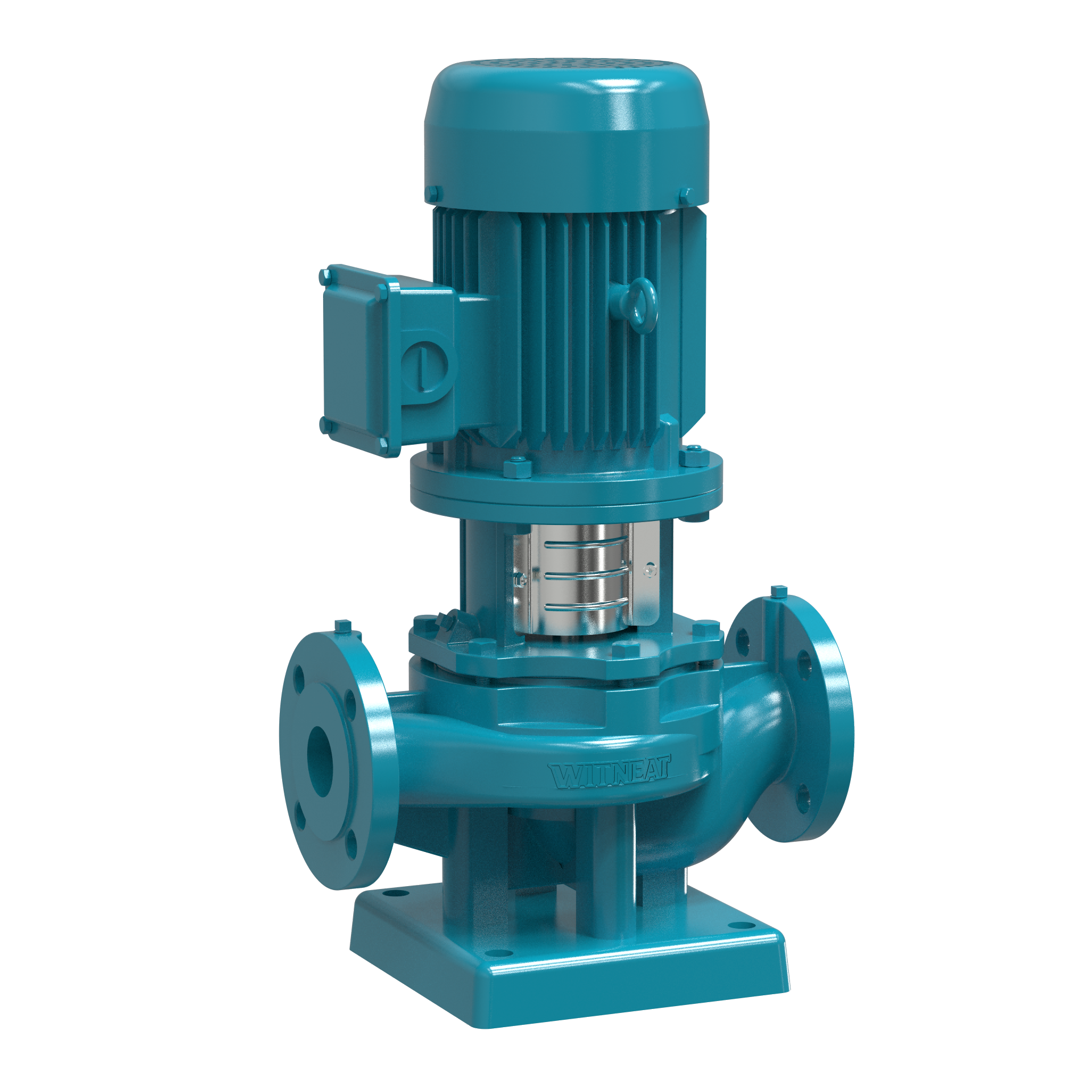
CDLF vertical multi-stage centrifugal pumps of WYT
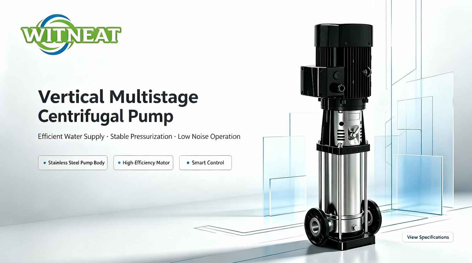
The operating principle of CDLF vertical multi‑stage centrifugal pumps
The applications of CDLF vertical multi‑stage centrifugal pumps
To ensure correct pump operation, it is crucial to pick the right product with respect to the application and the chemical‑physical characteristics of the fluid being treated.
High‑rise building water supply Pressure boosting for residential and commercial high‑rise buildings, zoned water supply for water‑works, pipeline network pressurisation for municipal water distribution systems.
General Industries Industrial process water circulation, cooling and air‑conditioning circulating systems, high‑pressure washing and cleaning lines, machine‑tool auxiliary water circuits, boiler feedwater and condensate recovery systems.
Water Treatment CDLF vertical multi‑stage centrifugal pumps are widely adopted in water‑treatment workflows, including reverse osmosis systems, ultra‑filtration units, distillation equipment and swimming‑pool water circulation. Wetted stainless‑steel components resist mild chemical attack for reliable handling of treated water and low‑corrosive process fluids.
CDLF vertical multi‐stage centrifugal pumps vs water pump
| CDLF vertical multi - stage centrifugal pumps | Water pumps | |
| Structure | Vertical, multi-stage (multiple impellers in series on one shaft) | Horizontal or vertical, single-stage / simple structure |
| Working principle | Centrifugal force + stage-by-stage pressurization by series impellers; total head is the sum of all stages | Centrifugal force produces pressure; single-stage pressurization |
| Head / Pressure | High head (from tens up to hundreds of meters), medium-high pressure | Low to medium head (usually a few to tens of meters) |
| Flow range | Low-to-medium flow matched to head (typically 2 - 30 m³/h) | Wide flow range, can reach very large capacities |
| Impeller | Multi-stage closed / semi-open impellers in series | Single-stage impeller (mostly closed type) |
| Self-priming | Non-self-priming; requires pre-filling / priming before start-up | Varies: general centrifugal pumps non-self-priming; self-priming type available |
| Installation | Vertical, inlet and outlet on the same plane, inline installation like a valve | Mostly horizontal, requiring baseplate and coupling alignment |